| Part | Explanation/Differences |
|---|---|
| DS18B20 | The one used here: TO-92 case, accuracy ±0.5 degrees (Celsius), user configurable resolution up to 12 bit (=0.0625°C) |
| DS18B20+ | Exactly the same as DS18B20, the + denotes that the product is lead free (this is a requirement in all european countries now, the keyword is "ROHS") |
| DS18S20 | resolution fixed at 9 bit (=0.5°C) |
| DS1820 | resolution fixed at 9 bit, a little faster, but no longer available |
| DS1822 | accuracy ±2 degrees (C) |
| # | Name | Comments |
|---|---|---|
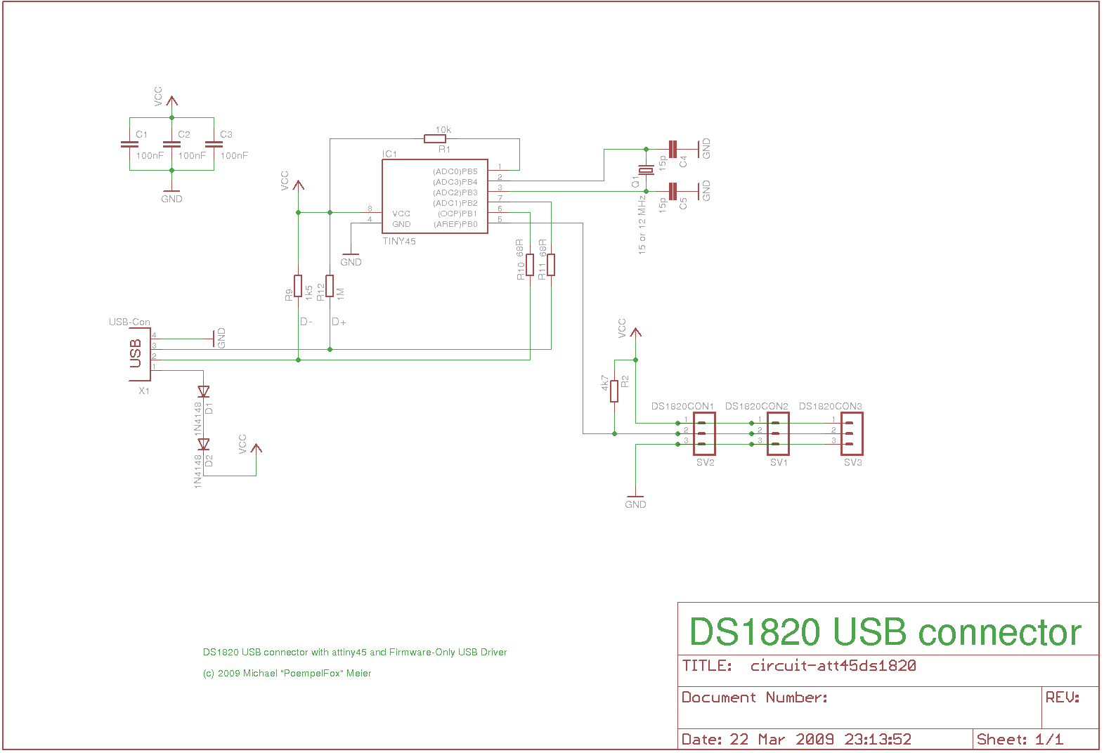
| 1 | ATtiny85 |
The main microcontroller doing all the work. You should get an ATtiny85 instead of the ATtiny45 I used originally to be on the safe side. See the remarks in the [Software] section. You will also need some programmer to flash the microcontroller with the firmware. |
| >=1 | DS18B20 | At least one temperature probe would make sense for a device that is intended to be used for temperature measurement... |
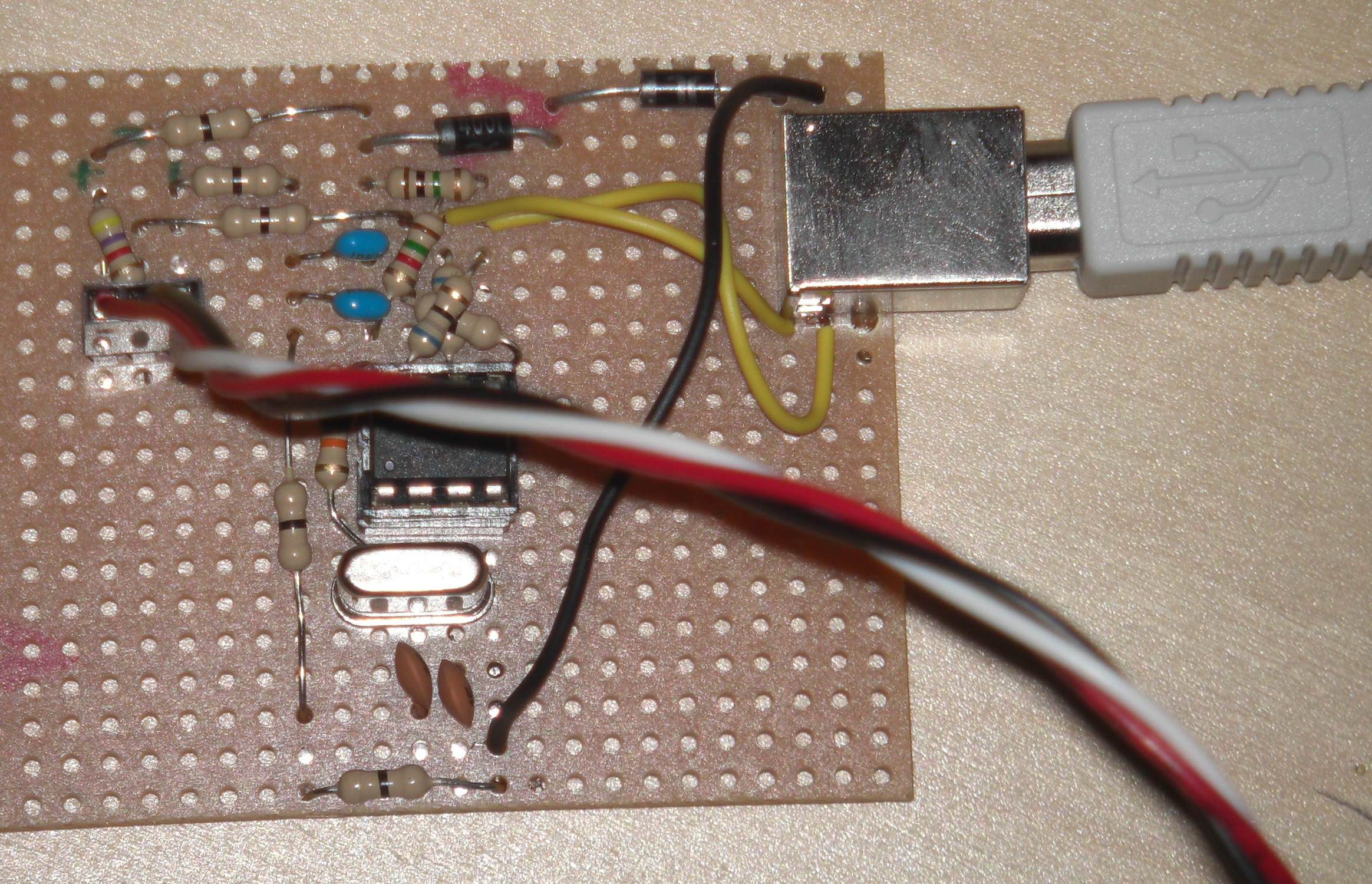
| 2 | Diode 1N4001 | These are abused to bring the supply voltage down from 5 to 3.6 Volts. Other silicium diodes (e.g. 1N4004, 1N4148) can be used as well, as long as they cause 0.6-0.7 volts of voltage dropout each. |
| 2 | Resistor 68Ω | |
| 1 | Resistor 1MΩ | |
| 1 | Resistor 1.5kΩ | |
| 1 | Resistor (<=) 4.7kΩ | This is the pullup for the 1wire bus. You might need to use a resistor with a smaller value for longer cables. |
| 1 | Resistor 10kΩ | This one is merely optional, it is a pullup resistor for the ATtinys !reset pin. The ATtiny has an internal pullup, so it's not strictly needed, but supposedly increases stability when the power supply is unstable. |
| 2 | Capacitor 100nF | These are used for stabilizing power. They can be larger than 100nF and there can be more than two. But you should put at least one close to the microcontroller and one close to the connection point for the probes. |
| 2 | Capacitor 15pF | according to the ATtiny datasheet, everything between 12 and 22 pF should be fine. |
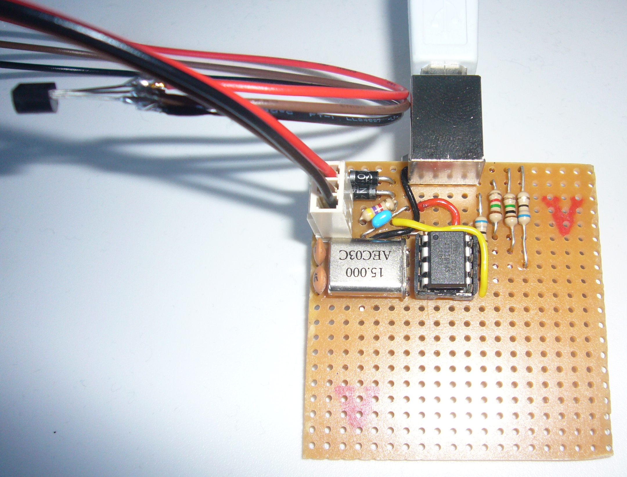
| 1 | Crystal 15 MHz | 12 MHz can probably be used as well, but that requires a minimal firmware change and hasn't been tested. |
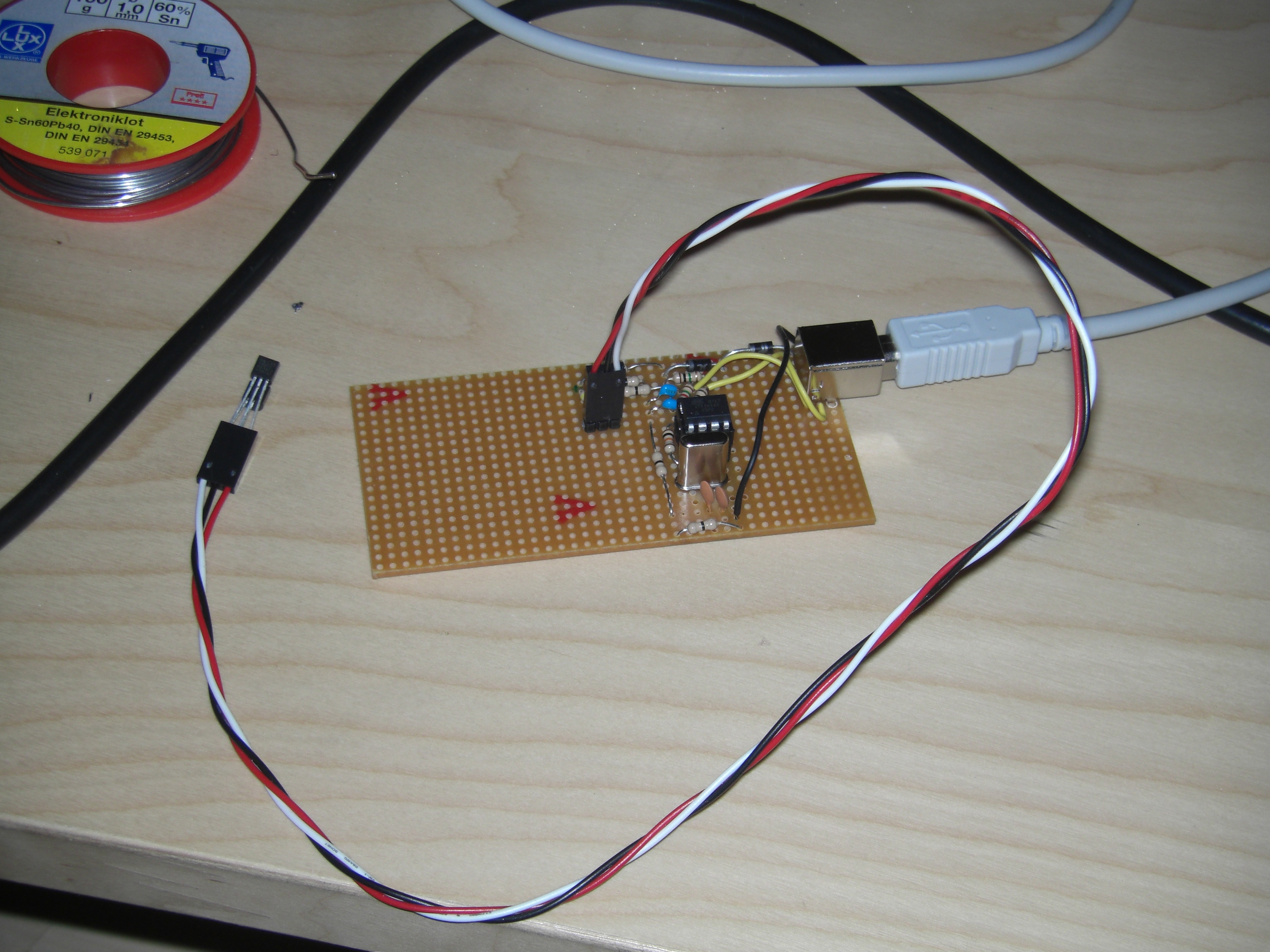
| 1 | DIP 8 socket | Recommended, else you would have to directly solder the ATtiny. |
| 1 | USB connector | Either use a proper USB jack like in the pictures, or just cut some USB cable open and directly solder the leads. |
Device Version is 00.01 Device time is currently timestamp 60742 4 probes supported by device fa serial fl lastseen ticksago lastvalue 28 000001efea9d U 60574 168 22.06 28 000001efe323 U 60635 107 22.12 00 000000000000 0 60742 0.00 00 000000000000 0 60742 0.00
Here, the device has found two temperature sensors. It could handle two more, but only two have been detected.