NTP DCF77 LED Clock

[..] [Introduction] [History] [DCF 77 Receiver] [LED Module] [Mainboard] [Clockface] [Software] [Acknowledgements] [Copyright/Disclaimers]


there also is a little [Video]

Introduction / What is it

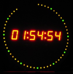
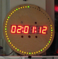
It is a clock with a big display unit, that has a DCF77 (german timesignal) Receiver and can be connected to an ethernet network, where it can serve as a (S)NTP server. All of this based on an Atmel AVR microcontroller with 8 KB flash.

History

This chapter contains a lot of blabber, so yoy can safely skip it.
Somehow the idea emerged, that the HaWo Networking Team needed a nice clock for their "Office".
However, just a normal clock wasn't considered 31337 enough. A first clock was created fast and cheap by taking a standard analog clock module and putting it behind a clock face that consisted of a printed circuit board with some additional fake chips on it.
As that still wasn't considered 31337 enough, the next idea was to make a clock connected to the network that could get its time through NTP (Network Time Protocol).
It was apparent that some sort of a microcontroller was needed for that, but at first nobody volunteered for that project.
Since I had been wanting to play with microcontrollers for a long time, one day I decided to give it a try.
After some research on the Internet, I made the decision to try it with an Atmel AVR.
There were some designs on the net very similiar to what I was trying to do: eAVR (whose webpage doesn't exist anymore, but as David Ritchie told me you can find an old copy of http://avr1.org/eavr/eavr.html on web.archive.org), Ulrichradig, "breadboard" PicoWeb to name just a few. I especially liked the idea of using old ISA NE2000 cards instead of new (expensive and close to impossible to solder) chips for the job, since there were a lot of these old cards lying around.
For first experiments, I got myself a STK500 Developer Board. These aren't exactly cheap at around 90€, but at least it makes sure that if something doesn't work then your code is to blame, and not the hardware - which is very useful for first experiments.
The project was broken into three parts that were mostly independent from each other: A DCF77 Receiver, a display module and finally, the mainboard, containing the ISA slot for the NE2000, some memory and the Atmel Microcontroller. The DCF Receiver and the display module could both be finished before the mainboard and tested on the STK500.
You may ask why the clock needs a DCF77 receiver if it is supposed to get its time from the network through NTP. Well, the simple answer is that at some point during the design phase megalomania struck, and so instead of only being a NTP client the clock was suddenly to become a NTP server...
For designing the circuit boards, I needed some software.
At first I tried Cadsoft Eagle. Since I am using Linux, the availability of a native Linux version was a big plus. Eagle left a very good impression, and I thought I had found the perfect tool for the job, until I had a look at the pricelist. There just isn't any version available that I could afford. The free version is limited to a PCB size hardly bigger than a finger nail, and the version that I would have needed, capable of creating standard euro-card PCBs (an ISA slot unfortunately is rather big!), costs more than 400€ according to their website. This apparently is a little bit too much for an average home user like me just playing around a bit. One can only hope they overthink their prices and offer some home-user-version with reasonable limits (2 layers, 160x100mm would do) one day...
So I had to search for other solutions. I found Target 3001. Though I did not like it as much as Eagle, and it does not have a native Linux version, it does run in Wine, and it has one very big advantage: There is an affordable version sufficient for what I was trying to do. Target does not limit board size like Eagle does, but instead limits the number of pins in a board. This makes a lot more sense in my opinion, since it doesn't force the use of small and error prone boards with SMD chips instead of properly sized and a lot easier to solder boards with DIP chips that have enough space between parts. The free version of Target allows 100 pins in a board, the "Light" version I aquired from Reichelt for around 40€ allows 400, which is a very reasonable limit for home users. I seriously doubt people will often build boards with more than 400 pins for home use.

The DCF77 Receiver

Since I had no idea how to do it myself, and the module was affordable, I just used a standard DCF77 Receiver module from Conrad. This module (stock number 641138) is only 35 x 20 millimeters in size, and includes an antenna. It only needs a power supply of 1.2 to 15 Volts, and has two outputs: One for the DCF signal, and one for the inverted signal. With pullup-resistors, you can use these outputs as input for the microcontroller.
In this case, I connected the signal output to the Atmels INT1 pin, enabled the internal pullup resistor for that port and set it to generate an interrupt whenever the signal changes from 0 to 1 or from 1 to 0, so that the interrupt routine can easily decode the DCF signal.

The LED Module

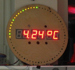
The initial reason for building all this was to have a nice big clock that could be put up on the wall. For that purpose, clearly a big display unit was needed. However, I had to settle for a compromise: The 100 mm big 7 segment digits I wanted were just unaffordable to me at 12€ a piece. So I had to settle for the "tiny" 57 mm digits for 3.40€ each. There are 6 of them, so that HH:MM:SS or alternatively DD.MM.YY can be displayed. There are blinking dots made with 10 mm LEDs between the hours and minutes resp. minutes and seconds. This makes the whole display a little more than 30 centimeters wide and 7 centimeters high.
The module is controlled by a little board with two SAA1064 display drivers. I wanted to use a MAX7219 first, which (judging from the data sheet) has a lot more power than the SAA1064, can be programmed faster, has a way higher refresh-rate, and the advantage that a single MAX7219 could drive all the digits. However, the 7 segment digits mentioned above internally consist of four LEDs in a row in each segment, each requiring a forward voltage of 1.85 volts. As you can easily calculate, the total forward voltage required by one such digit is thus 7.4 volts, and that is way more than the 6 volts the MAX7219 can tolerate as supply voltage.
The SAA1064 can run at up to 15 V, but even with this supply voltage it has a 5 V I2C Bus slave interface. This is of course perfect for this application, since the Atmel will run at 5V and act as the I2C master. Since a single SAA1064 can only drive 32 LEDs, there are two of them, and since it is rated for only 100 mA on the multiplex pins, but the digits will draw significantly more, transistors are used to amplify the power supplied to the common anode of the 7 segment digits.
You can see a "beta version" of the LED module (still missing the four dots) in action here.
Part List: (the stock numbers were valid in March 2005, but of course they may have changed)
# Reichelt Stock Nr. Description Part-Nr. in the drawings
2SAA 1064LED-Driver, DIL-24IC1, IC2
2GS 24IC Socket, 24 pinsN/A
2KERKO 2,7NCapacitor, 2.7nFC1, C2
12PS 25/5G WSconnector, 5 pinsK2 - K13
1PS 25/3G WSconnector, 3 pinsK1
1PS 25/2G WSconnector, 2 pinsK18
4SL 1X36G 2,54 (?) connector, 2 pins - these are just the normal pins you would use for jumpers. K14 - K17
1FHPCU 160x100Photo coated copper boardN/A
4BC 140-10Transistor BC140T1 - T4
3AX 100/25Electrolyte capacitor, 100µFC3 - C5
21N 4001Diode 1 N 4001D9, D10
1?Power supply connectorBu1
1LED 5MM ST RTstandard LED red (to show wrong supply polarity)LED10
1LED 5MM ST GNstandard LED greenLED11
1METALL 560resistor, about 500 Ohm (for the 2 LEDs above)R1
8LED 5MM R OR2.5 x 5 mm rectangular LED orangeLED1 - LED8
3SPL 20 IC Socket with only one row (used for the 7 segment digits, they are not directly soldered onto the board, but instead get mounted on these) N/A
6SA 23-12 RT 7 segment LED digits, 57 mm digit height, Kingbright SA23-12SRWA (Super Bright Red, Common Anode) N/A
4LED 8-4500 RT big LEDs (for the dots), grinded so they got a flat top N/A

Downloads:
Schematics
PCB Layout
Assembly Plan
Target 3001 file
PCB Layout of the Panel on which the digits get mounted

The Mainboard

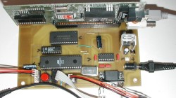
This is a really nice board with a lot of features that could make it useful for a lot of other applications as well. I got the idea from Jason Kyle's eAVR Project (sorry, project page is dead at the time of writing this).
The board has the following features: Unfortunately, when designing the board, I did not pay enough attention to the pinout of the ISP-connector. Of course, the numbering of the pins in the STK500 manual was not the same as the numbering in Target3001, in fact, they are as different as possible, not a single pin except pin 1 matches. So to use the programming connector on the PCB, an adapter that corrects the pinout had to be built. Should you plan to use this board layout, fix the programming connector before you do.
Apart from this glitch, building the board went surprisingly smooth. It worked just fine from the beginning.
Pictures of the Mainboard: Top Bottom

Part List: (the stock numbers were valid in March 2005, but of course they may have changed)
# Reichelt Stock Nr. Description Part-Nr. in the drawings
1BEL 160x100-1Photo coated copper boardN/A
1GS 40IC Socket, 40 pinsN/A
1ATMEGA 8515-16Microcontroller, DIP40IC1
174HCT 5738 bit flipflopIC2
162256-80SRAM, 32Kx8IC3
1OSZI 8,000000Oscillator, 8 MhzQ1
1 MAX 232 ECPE Serial Interface Converter (+5V TTL -> ±12V RS232) IC4
1 LM 1084 IT5,0 Voltage Regulator 5V, 5A.
NOTE: Heatsink required!
IC6
1STECKER 62-2548 bit ISA slot (2 x 31 pins)ISA1
1TASTER 1082.3nice red Reset-ButtonK11
21N 4001Diode, 1AD1, D2
4MKS-2 100NCeramic Capacitor, 100nFC3, C4, C6, C7
2RAD 100/25Electrolyte Capacitor, 100uF (standing)C5, C8
2AX 100/25Electrolyte Capacitor, 100uF (lying)C1, C2
1METALL 10,0KResistor, 10KR1
1D-SUB ST 09EUSerial PortK2
1?Power supply connectorBu1
...and various connectors not listed here (use what fits you best, or use the ones from the LED module part list).

Downloads:
WARNING: These files contain the board as it was built, including the broken ISP connector! For details see the text below the featurelist.
Schematics as built (contains error!)
PCB Layout as built (contains error!)
Assembly Plan (contains error!)
Target 3001 file (contains error!)
Target 3001 file (corrected, but untested)

The Clockface

Megalomania struck again, so we built a clockface with 60 LEDs that show the seconds. Diameter 45 cm. No superbright LEDs though, only standard LEDs. Driven by a MAX7219. There is no schematics for this, as it really just is built like in the datasheet (and not on a printed circuit board).

The Software

The Software was written from Scratch in C, and compiled with AVR GCC. AVR GCC allows you to use wide integer types (up to 32 bit) without having to worry about the gory details of getting that into the (8 bit) microcontroller, while at the same time allowing to interfere at a very low level, e.g. activating the external memory interface as one of the first initialization steps (even before global variables are created).
Though the software was written from scratch, I peeked into other software solutions to see how they did it of course. Worth mentioning are especially Dave Clausen's AVR Ethernet Assembler-Sources, because they helped me a lot in getting the NE2000 to work, and some AVR NTP project, which gave me some very nice ideas that helped me implement the NTP server.
The software currently has the following features: Downloads:
Sourcecode v 1.00 (10. May 2006) - there is also a .bin for flashing into the AVR here, but you'll have to "compile" the EEPROM containing data like the IP address yourself in any case.
Old version: Sourcecode v 0.90 (1. May 2005)

Acknowledgements

The following people helped a lot with the implementation of the clock:
Alexander "arw" W. Most of the Soldering, ...
Rolf "waijb" W. Supplied me with his Osram Ultra Vitalux 300W for exposing of the boards (very good lamp for doing this!) and some chemicals for etching.
Martin "deluxe" P. Some soldering, most of the clockface
Tobias "knilch" J. Drilled the boards for mounting the 7-segment led digits with his gimlet, and killed one of my precious 0.9 mm drills in the process.
Frank "Frunk" N. Helped out with his gimlet - in contrast to knilch he actually knows how to use such a thing.

Copyright/Disclaimers

All trademarks are property of their respective owners.
Should you try to rebuild anything shown or use anything offered here, you do so at your own risk.
Your mileage may vary.
All plans and software are released under the GNU GPL.