NTP GPS LED Clock
[..]
[Introduction]
[History]
[Mainboard]
[Display]
[Software]
[Known problems]
[Acknowledgements]
[Copyright/Disclaimers]
[Feedback]
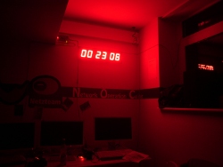

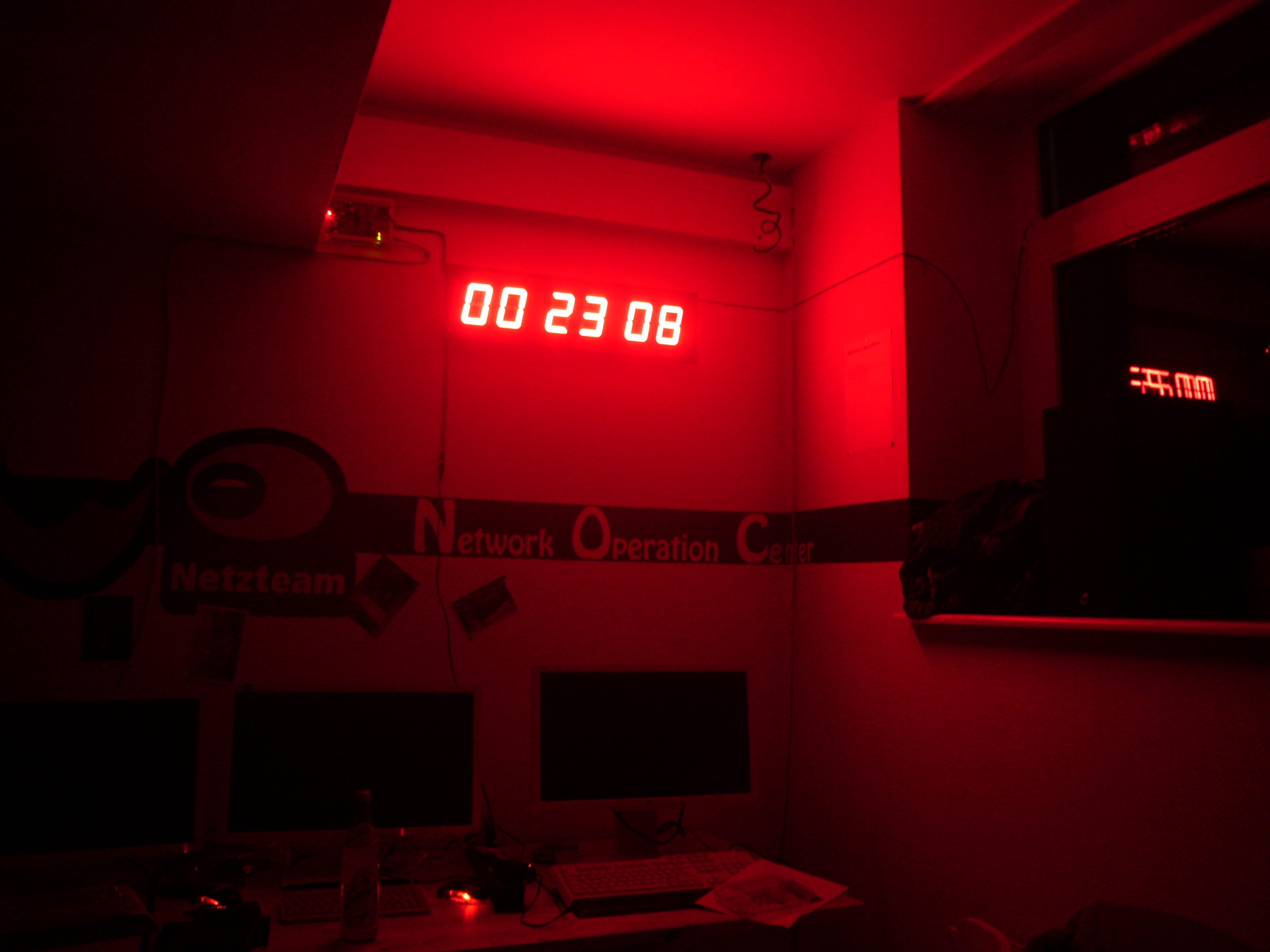
Introduction / What is it
It is a clock with a big display unit, that has a GPS receiver from
which it gets its timesignal, that can be connected to an ethernet network, where
it can serve as a (S)NTP server. All of this based on an Atmel
ATMEGA328 microcontroller.
Unfortunately, this isn't a project that I would call properly finished,
and considering how many years it has been in the makings, it
probably never will be. There are a number of hardware- and
software-problems that were never quite worked out. I still
publish it, because who knows, somebody else might reuse it or
fix it up?
History
This is the successor of the NTP-DCF77-LED-Clock
that I built (together with a few others) a few years ago.
It is a new design from scratch. Reasons for the rebuild were a few:
- As nerdy-cool as the use of an old ISA-network-card was, it had
a few downsides, namely that it took up huge amounts of space,
and that those cards haven't been manufactured for many many
years, making it harder to come by a working one.
- The 8 KB flash on the old design were completely full,
literally to the last byte, I had to shorten the command-line
prompt by one byte to make it fit,
and there was no drop-in replacement for the microcontroller
with more flash
available, making any extensions like IPv6 support
impossible. In fact, it hasn't been possible to compile
the firmware with recent avr-gcc and avr-libc for a few
years now, as they would generate slightly larger code
that wouldn't fit into 8 KB anymore.
- The accuracy of DCF77 with the simple receiver used
is only about 0.1 seconds, which is way too bad for
proper NTP use - GPS should give much better accuracy
(less jitter).
- SOMEBODY dropped the old clock, causing some damage
including breaking one of the boards on which the
digits were mounted. It never could be properly repaired,
a slack joint always remained.
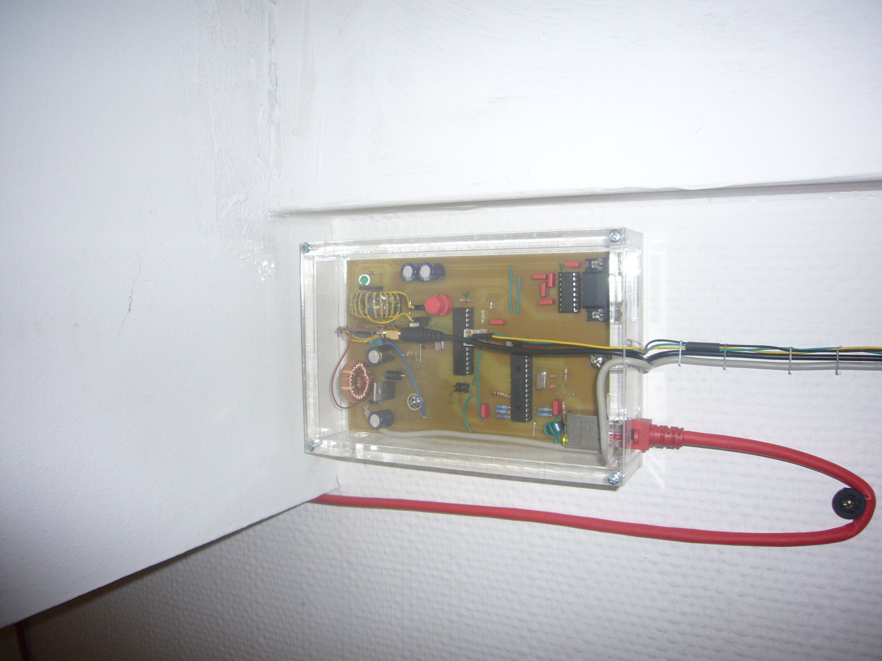
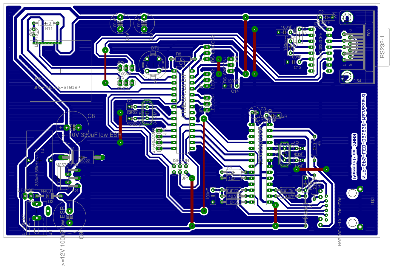
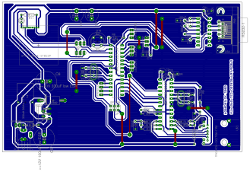
The Mainboard
This is a single-sided euro-size (160x100 mm) board
housing everything that is needed. Mainly the microcontroller
(an ATmega328), the networking chip (ENC28J60) and miscellanous
other stuff. There was also space for a certain GPS module,
it could be mounted onto the mainboard - this module was later
replaced by a different one which has different connector
positions and is a different size. The board was designed
so that the main parts (the microcontroller and the networking)
could be reused for other projects, by simple replacing the
stuff surrounding them.


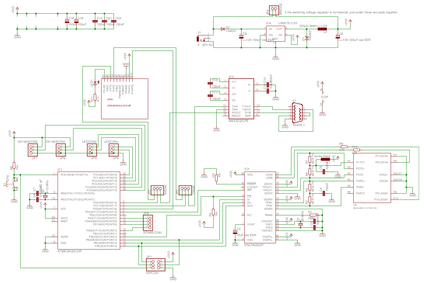
The schematics (Eagle files) are included with the
software download below.
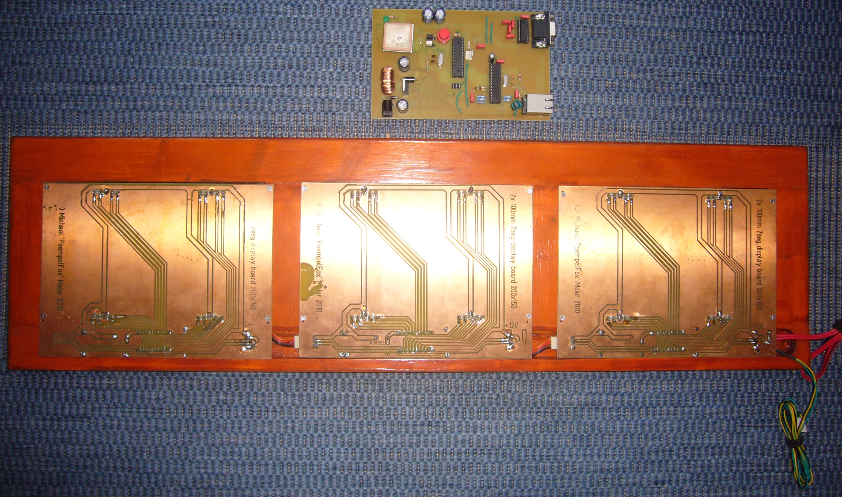
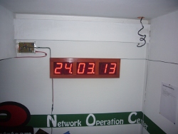
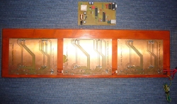
Display Unit
This consists of three identical single-sided boards,
each 200x150 mm,
each containing two 100 millimeter high
7-segment digits (SA40-19SRWA) and an SAA1064 chip to control them.
They are addressed through an I2C-Bus that runs
through all of them (and each of the three boards gets
assigned an individual address on the bus by soldering in
a jumper or two resistors).
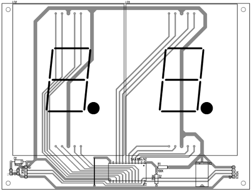
The boards were constructed with Target 3001 (because their
size was too large for my low-end version of eagle).
board for two 7-segment digits (PostScript)
board for two 7-segment digits (Target3001 file)
The Software
The Software was written from Scratch in C, and compiled with AVR GCC.
Downloads:
Sourcecode v0.01 (06. Apr 2012)
With a bit of luck, you might find a newer version in
this
public gitweb repository.
Known problems, or: why I would not call this project finished
There are multiple problems with the hard- and software that
were never properly ironed out. These include, but are not limited
to:
The software
The software was never quite finished. Functionality is missing.
Also, in particular the networking "stack"
is a big piece of crappy code that is almost impossible to read or
debug and should be rewritten from scratch.
The GPS receiver
There is a fundamental problem here that I did not realize
beforehand: While you do get a time signal from GPS as a
by-product, support for getting this signal out of the
receiver is completely broken in the firmware of most GPS
modules, even if the modules have a "PPS" pin
for signalling the start of a new second.
The first module that was tried and that you can see in
all the schematics was the ST01SP that AFAIK was also the
base of one of the first versions of Mr.
Lee CatTrack. It does offer a PPS pin, but unfortunately,
had a firmware that is not at all suitable for the purpose of
getting the time out of it. For starters, it did not support
activating the GPZDA message (a message dedicated to getting
time) in the NMEA output, so you needed to parse
the GPRMC message instead. And it most of the time (but not always)
had a constant 2 second offset
to the correct time - apparently, because the firmware used a hardcoded value
for the number of leap seconds, and there had been two other
leap seconds since the module was produced that it did not know
about. We also had problems mounting the module so that it would
get GPS reception since it did not support connecting an external
antenna.
So we finally decided to try a different module, and got
the GPS-10921.
Of course this did not fit our mainboard, so it is connected
through wires and fitted with glue, which looks a bit ugly,
but works. Thanks to
the external antenna connector, getting a signal was a lot easier,
and the firmware was better too, but still not perfect: It
does support the GPZDA message, but you do not get the message at
the start of a second, only somewhere in between. This unfortunately
is very problematic: Assume you get a PPS pulse, and afterwards the
GPZDA message with a timestamp of say 12:00:00.900. This can happen,
because naturally the serial transmission takes some time, while
the PPS signal is instantly delivered. It tells you that the pulse
you just got was the pulse for 12:00:01.000, not the one
for 12:00:00.000 as you might have originally thought. It means
you have to make some guesses as to which second a pulse was
actually for, and unfortunately, I never managed to implement
a stable heuristic for that.
Bugs
There are some bugs, and it isn't exactly clear if they are
in hard- or software. As the clock is now mounted to the wall,
debugging them is almost impossible for me and will probably
never happen because I'm a lazy bastard.
- The clock display sometimes jumps back and forth, i.e.
12:00:00 -> 12:00:01 -> 12:00:00 -> 12:00:01.
This is most probably an effect of the GPS problem
described above but might also be unrelated.
- The network stops responding after some time.
Acknowledgements
Andreas "llandon" Schwarz helped a lot with
the clock, and built all of the casing.
Copyright/Disclaimers
All trademarks are property of their respective owners.
Should you try to rebuild anything shown or use anything offered here,
you do so at your own risk.
Your mileage may vary.
All plans and software are released under the
GNU
GPL.
Feedback?
You can post feedback under the Blog
Article referring to this.